ECE 4750 Section 12: Networks
- Author: Christopher Batten
- Date: November 18, 2022
Table of Contents
- Network Overview
- Implementing and Testing the Route Unit
- Implementing and Testing the Switch Unit
- Implementing and Testing the Router
This discussion section serves as a basic introduction to networks which
will help students implement a simple ring network for lab 4. You should
log into the ecelinux servers using the remote access option of your
choice and then source the setup script.
% source setup-ece4750.sh
% mkdir -p $HOME/ece4750
% cd $HOME/ece4750
% git clone git@github.com:cornell-ece4750/ece4750-sec12-net sec12
% cd sec12
% TOPDIR=$PWD
% mkdir $TOPDIR/build
Network Overview
In order to implement the multicore processor shown below, we will need to implement three networks: a cache network that interconnects each processor’s data memory interface to each of the four data cache banks, a memory network that interconnects each data cache’s memory interface to main memory, and a memory network that interconnects each instruction cache’s memory interface to main memory.
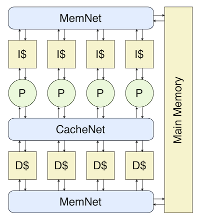
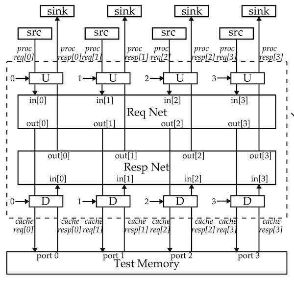
The cache network actually includes two networks: one that enables processors to send cache requests to the caches and one that enables caches to send cache responses back to the processors. We also need adapters at the network interfaces to convert to/from memory messages and network messages.
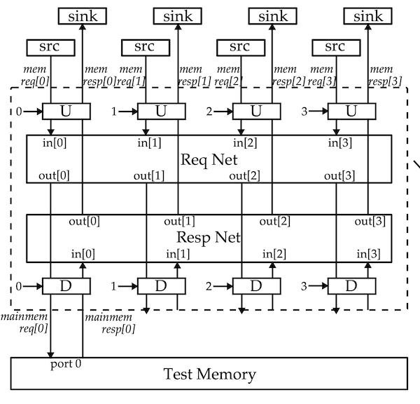
The memory networks also include two networks. The primary differences it that there is only a single destination.
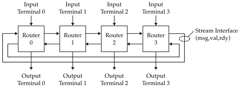
More generally, a network enables sending messages from a set of input terminals to a set of output terminals. Bus and crossbar networks use long global wires that every input terminal can write and every output terminal can read.
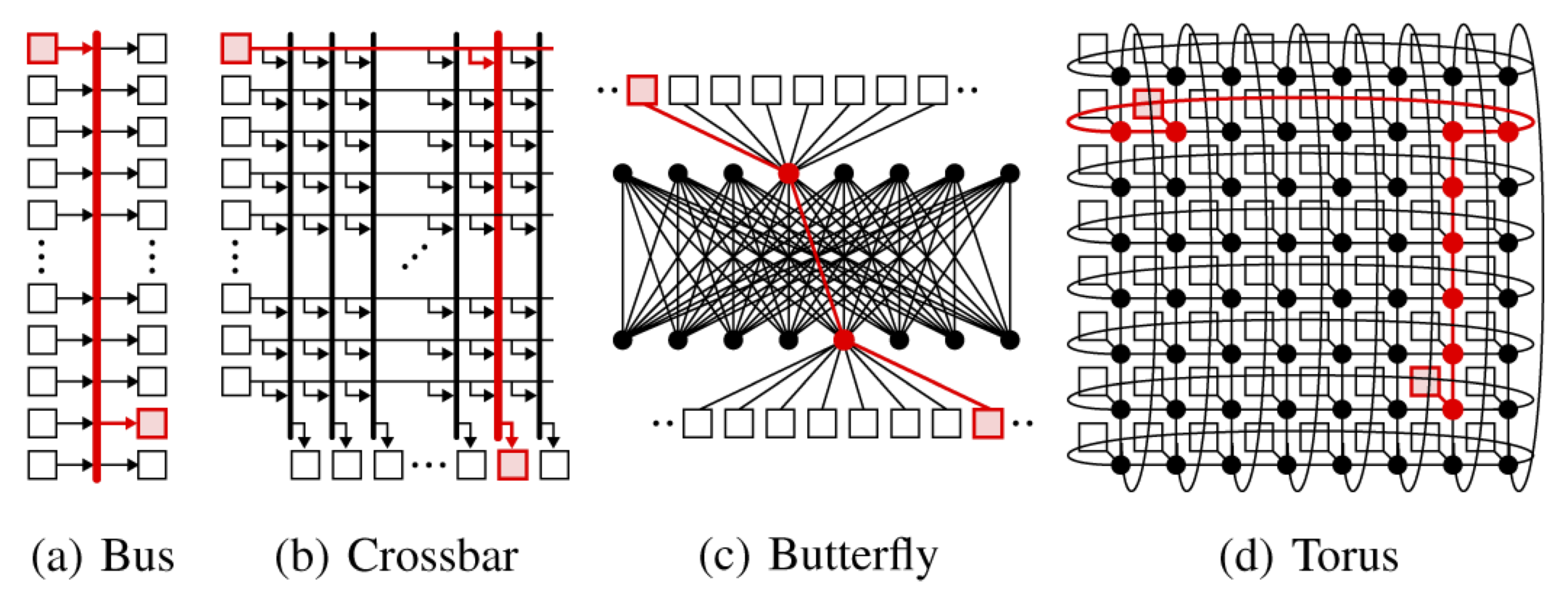
Bus topologies are simple but offer low throughput. Crossbar topologies enable higher throughput, but are also more expensive in terms of area and energy. Scalable networks use a set of smaller routers interconnected by shorter channels to create a network topology. Examples include butterfly and torus topologies. In lab 4, you will be implementing a simple 1D torus topology (i.e., a four node ring) which only uses nearest neighbor communication.
In addition to the network topology, a network microarchitecture will also need to implement a network routing algorithm (what path should we take to get from a given input terminal to a given output terminal?) and a network arbitration algorithm (how should we allocate resources like ports and buffers?).
We can use zero load latency and ideal terminal throughput to analyze the first-order performance of a network. The zero load latency is the number of cycles it takes for a message to go from the input terminals to the output terminals assuming a specific traffic pattern. The ideal terminal throughput is the maximum achievable throughput an input terminal can achieve assuming a specific traffic pattern, a perfect routing algorithm, and a perfect flow control scheme. We will analyze the zero load latency and ideal terminal throughput of our simple four node ring network topology together in the discussion section.
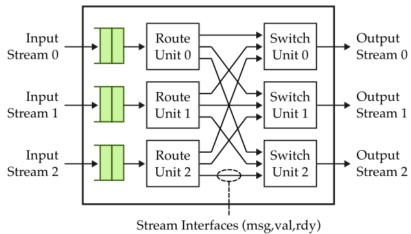
Each router in our network will have three input streams and three output streams. All streams are latency insensitive using the val/rdy microprotocol. We will use the following router microarchitecture which includes three input queues, three route units, and three switch units. The route units implement the routing algorithm and determine which output stream a given input message should be sent, while the switch units implement the arbitration algorithm and determine which input stream can send a message to an output stream on any given cycle.
All of our networks will work with network messages (also called packets) that use the following format.
 43  42 41  40 39    32 31            0
+------+------+--------+---------------+
| src  | dest | opaque |    payload    |
+------+------+--------+---------------+
This network message is shown with a payload of 32 bits, but our networks will actually be parameterized by the payload size so we can use a single network implementation in the cache request network, cache response network, memory request network, and memory response network.
Implementing and Testing the Route Unit
We will start by implementing a very basic route unit. Take a look at the
route unit in lab4_sys/NetRouterRouteUnit.v. The interface looks like
this:
module lab4_sys_NetRouterRouteUnit
#(
  parameter p_msg_nbits = 44
)
(
  input  logic                   clk,
  input  logic                   reset,

  // Router id (which router is this in the network?)

  input  logic     [1:0]         router_id,

  // Input stream

  input  logic [p_msg_nbits-1:0] istream_msg,
  input  logic                   istream_val,
  output logic                   istream_rdy,

  // Output streams

  output logic [p_msg_nbits-1:0] ostream_msg [3],
  output logic                   ostream_val [3],
  input  logic                   ostream_rdy [3]
);
The route unit has one input stream interface and three output stream
interfaces. Notice the [3] at the end of the output stream ports. This
is new Verilog syntax for modeling an array of ports. The route unit we
will implement in the discussion section will simply use the destination
field of the network message to determine the output port. For the ring
network, you will need to implement a more complicated route unit that
picks an output port based on your desired routing algorithm and the
current router’s id.
Go ahead and complete the implementation of the route unit. You want to first check to make sure the input stream is valid, check the destination field, and use the destination field to set the appropriate output stream valid signal and input stream ready signal. Here is a sketch of the logic you will need.
if ( istream_val ) begin
  if ( istream_msg_hdr.dest == 0 ) begin
    istream_rdy = ostream_rdy[0];
    ostream_val[0] = 1;
  end
  else if ( istream_msg_hdr.dest == 1 ) begin
    istream_rdy = ostream_rdy[1];
    ostream_val[1] = 1;
  end
  else if ( istream_msg_hdr.dest == 2 ) begin
    istream_rdy = ostream_rdy[2];
    ostream_val[2] = 1;
  end
end
You can also directly use the destination field to index into the output stream val/rdy port arrays. Once you have finished you can test your route unit like this:
% cd $TOPDIR/build
% pytest ../lab4_sys/test/NetRouterRouteUnit_test.py
% pytest ../lab4_sys/test/NetRouterRouteUnit_test.py -k stream_to_all] -s
Use the -k and -s command line options to view the line traces for
specific test cases. Here is what the line trace looks like.
    src       d    sink0  sink1  sink2
 1r .      > ( ) >       |      |
 2r .      > ( ) >       |      |
 3: .      > ( ) >       |      |
 4: 0>0:00 > (0) > 0>0:00|      |
 5: 0>1:40 > (1) >       |0>1:40|
 6: 0>2:80 > (2) >       |      |0>2:80
 7: 0>0:01 > (0) > 0>0:01|      |
 8: 0>1:41 > (1) >       |0>1:41|
 9: 0>2:81 > (2) >       |      |0>2:81
10: 0>0:02 > (0) > 0>0:02|      |
11: 0>1:42 > (1) >       |0>1:42|
12: 0>2:82 > (2) >       |      |0>2:82
13: 0>0:03 > (0) > 0>0:03|      |
14: 0>1:43 > (1) >       |0>1:43|
15: 0>2:83 > (2) >       |      |0>2:83
16: 0>0:04 > (0) > 0>0:04|      |
17: 0>1:44 > (1) >       |0>1:44|
You can see the network messages are being sent to each of the three
output ports based on the destination field. The d column indicates the
destination field.
Implementing and Testing the Switch Unit
Next we need to implement a very basic switch unit. Take a look at the
switch unit in lab4_sys/NetRouterSwitchUnit.v. The interface looks like
this:
module lab4_sys_NetRouterSwitchUnit
#(
  parameter p_msg_nbits = 44
)
(
  input  logic                   clk,
  input  logic                   reset,

  // Input streams

  input  logic [p_msg_nbits-1:0] istream_msg [3],
  input  logic                   istream_val [3],
  output logic                   istream_rdy [3],

  // Output stream

  output logic [p_msg_nbits-1:0] ostream_msg,
  output logic                   ostream_val,
  input  logic                   ostream_rdy
);
The switch unit has three input stream interfaces and one output stream
interface. Again, notice the [3] at the end of the input stream ports
which is used for modeling an array of ports. The switch unit we will
implement in the discussion section will simply use a fixed priority. If
multiple input ports want to use a given output port, we give highest
priority to the input stream 1 and the lowest priority to input stream 0.
We choose this priority, because when we use this switch unit in the
router we ideally want to give higher priority to messages already in the
network (i.e., input streams 1 and 2) over messages that are waiting at
the input terminal (i.e., input stream 0). This simple switch unit will
actually work in the ring network, but it could perform poorly since it
does not attempt to provide any kind of fair arbitration across the input
ports.
Go ahead and complete the implementation of the switch unit. You want to check each of the input stream valid signals in priority order and as soon as you find a valid input stream set the output stream valid bit, output stream message, and input stream ready signal appropriately. Here is a sketch of the logic you will need.
if ( istream_val[1] ) begin
  selected_input = 1;
  istream_rdy[1] = ostream_rdy;
  ostream_val    = 1;
  ostream_msg    = istream_msg[1];
end
else if ( istream_val[2] ) begin
  selected_input = 2;
  istream_rdy[2] = ostream_rdy;
  ostream_val    = 1;
  ostream_msg    = istream_msg[2];
end
else if ( istream_val[0] ) begin
  selected_input = 0;
  istream_rdy[0] = ostream_rdy;
  ostream_val    = 1;
  ostream_msg    = istream_msg[0];
end
You can also make this logic more succinct by first determining the selected input based on the fixed priority and then using the selected input signal to directly index into the input stream val/rdy port arrays.
Once you have finished you can test your route unit like this:
% cd $TOPDIR/build
% pytest ../lab4_sys/test/NetRouterSwitchUnit_test.py
% pytest ../lab4_sys/test/NetRouterSwitchUnit_test.py -k stream_from_all] -s
Use the -k and -s command line options to view the line traces for
specific test cases. Here is what the line trace looks like.
    src0   src1   src2      a    sink
 1r .     |.     |.      > ( ) >
 2r .     |.     |.      > ( ) >
 3: .     |.     |.      > ( ) >
 4: #     |1>0:00|#      > (#) > 1>0:00
 5: #     |1>0:01|#      > (#) > 1>0:01
 6: #     |1>0:02|#      > (#) > 1>0:02
 7: #     |1>0:03|#      > (#) > 1>0:03
 8: #     |1>0:04|#      > (#) > 1>0:04
 9: #     |1>0:05|#      > (#) > 1>0:05
10: #     |1>0:06|#      > (#) > 1>0:06
11: #     |1>0:07|#      > (#) > 1>0:07
12: #     |1>0:08|#      > (#) > 1>0:08
13: #     |1>0:09|#      > (#) > 1>0:09
14: #     |1>0:0a|#      > (#) > 1>0:0a
15: #     |1>0:0b|#      > (#) > 1>0:0b
16: #     |1>0:0c|#      > (#) > 1>0:0c
17: #     |1>0:0d|#      > (#) > 1>0:0d
18: #     |1>0:0e|#      > (#) > 1>0:0e
19: #     |1>0:0f|#      > (#) > 1>0:0f
20: #     |.     |2>0:00 > (:) > 2>0:00
21: #     |.     |2>0:01 > (:) > 2>0:01
22: #     |.     |2>0:02 > (:) > 2>0:02
23: #     |.     |2>0:03 > (:) > 2>0:03
24: #     |.     |2>0:04 > (:) > 2>0:04
25: #     |.     |2>0:05 > (:) > 2>0:05
26: #     |.     |2>0:06 > (:) > 2>0:06
27: #     |.     |2>0:07 > (:) > 2>0:07
28: #     |.     |2>0:08 > (:) > 2>0:08
29: #     |.     |2>0:09 > (:) > 2>0:09
30: #     |.     |2>0:0a > (:) > 2>0:0a
31: #     |.     |2>0:0b > (:) > 2>0:0b
32: #     |.     |2>0:0c > (:) > 2>0:0c
33: #     |.     |2>0:0d > (:) > 2>0:0d
34: #     |.     |2>0:0e > (:) > 2>0:0e
35: #     |.     |2>0:0f > (:) > 2>0:0f
36: 0>0:00|.     |.      > (.) > 0>0:00
37: 0>0:01|.     |.      > (.) > 0>0:01
38: 0>0:02|.     |.      > (.) > 0>0:02
39: 0>0:03|.     |.      > (.) > 0>0:03
40: 0>0:04|.     |.      > (.) > 0>0:04
You can see input port 1 has the highest priority so input port 2 does
not have a chance to send any messages until input port 1 is finish.
Input port 0 is the lowest priority and so it gets to go last. The a
column indicates how many input ports want to send to messages to this
switch unit.
.= one input port has a valid input message:= two input ports have a valid input messages#= three input ports have a valid input messages
So # indicates there is congestion at this switch unit.
Implementing and Testing the Router
Now that we have implemented and tested the route unit and switch unit,
we can compose them with the input queues to implement the three-port
router. Take a look at the switch unit in lab4_sys/NetRouter.v. The
interface looks like this:
module lab4_sys_NetRouter
#(
  parameter p_msg_nbits = 44
)
(
  input  logic                   clk,
  input  logic                   reset,

  // Router id (which router is this in the network?)

  input  logic     [1:0]         router_id,

  // Input streams

  input  logic [p_msg_nbits-1:0] istream_msg [3],
  input  logic                   istream_val [3],
  output logic                   istream_rdy [3],

  // Output streams

  output logic [p_msg_nbits-1:0] ostream_msg [3],
  output logic                   ostream_val [3],
  input  logic                   ostream_rdy [3]
);
The router has three input streams and three output streams. We have provided the composition for the router for you. Take a look at the implementation and notice the use of direct assignment to port arrays when instantiating the switch units:
lab4_sys_NetRouterSwitchUnit#(44) sunit0
(
  .clk          (clk),
  .reset        (reset),

  .istream_msg  (`{ runit0_ostream_msg[0], runit1_ostream_msg[0], runit2_ostream_msg[0] }),
  .istream_val  (`{ runit0_ostream_val[0], runit1_ostream_val[0], runit2_ostream_val[0] }),
  .istream_rdy  (`{ runit0_ostream_rdy[0], runit1_ostream_rdy[0], runit2_ostream_rdy[0] }),

  .ostream_msg  (ostream_msg[0]),
  .ostream_val  (ostream_val[0]),
  .ostream_rdy  (ostream_rdy[0])
);
The ```{}`` syntax is simple to the standard Verilog concatentation
operator {} but the extra back tick indicates that we are creating an
array of signals not a single bit vector. This compact code takes the
first stream from each of the three route units and connects them to the
first switch unit. You can test the router like this:
% cd $TOPDIR/build
% pytest ../lab4_sys/test/NetRouter_test.py
% pytest ../lab4_sys/test/NetRouter_test.py -k stream_all_to_dest0] -s
Use the -k and -s command line options to view the line traces for
specific test cases. Here is what the line trace looks like.
    src0   src1   src2      qqq sss    sink0  sink1  sink2
 1r       |      |       > (   |   ) >       |.     |.
 2r       |      |       > (   |   ) >       |.     |.
 3:       |      |       > (   |   ) >       |.     |.
 4: 0>0:00|1>0:00|2>0:00 > (   |   ) >       |      |
 5: 0>0:01|1>0:01|2>0:01 > (...|#  ) > 1>0:00|      |
 6: 0>0:02|1>0:02|2>0:02 > (:.:|#  ) > 1>0:01|      |
 7: 0>0:03|1>0:03|2>0:03 > (*.*|#  ) > 1>0:02|      |
 8: #     |1>0:04|#      > (#.#|#  ) > 1>0:03|      |
 9: #     |1>0:05|#      > (#.#|#  ) > 1>0:04|      |
10: #     |1>0:06|#      > (#.#|#  ) > 1>0:05|      |
11: #     |1>0:07|#      > (#.#|#  ) > 1>0:06|      |
12: #     |1>0:08|#      > (#.#|#  ) > 1>0:07|      |
13: #     |1>0:09|#      > (#.#|#  ) > 1>0:08|      |
14: #     |1>0:0a|#      > (#.#|#  ) > 1>0:09|      |
15: #     |1>0:0b|#      > (#.#|#  ) > 1>0:0a|      |
16: #     |1>0:0c|#      > (#.#|#  ) > 1>0:0b|      |
17: #     |1>0:0d|#      > (#.#|#  ) > 1>0:0c|      |
18: #     |1>0:0e|#      > (#.#|#  ) > 1>0:0d|      |
19: #     |1>0:0f|#      > (#.#|#  ) > 1>0:0e|      |
20: #     |      |#      > (#.#|#  ) > 1>0:0f|      |
21: #     |      |#      > (# #|:  ) > 2>0:00|      |
22: #     |      |2>0:04 > (# *|:  ) > 2>0:01|      |
23: #     |      |2>0:05 > (# *|:  ) > 2>0:02|      |
24: #     |      |2>0:06 > (# *|:  ) > 2>0:03|      |
25: #     |      |2>0:07 > (# *|:  ) > 2>0:04|      |
26: #     |      |2>0:08 > (# *|:  ) > 2>0:05|      |
27: #     |      |2>0:09 > (# *|:  ) > 2>0:06|      |
28: #     |      |2>0:0a > (# *|:  ) > 2>0:07|      |
29: #     |      |2>0:0b > (# *|:  ) > 2>0:08|      |
30: #     |      |2>0:0c > (# *|:  ) > 2>0:09|      |
31: #     |      |2>0:0d > (# *|:  ) > 2>0:0a|      |
32: #     |      |2>0:0e > (# *|:  ) > 2>0:0b|      |
33: #     |      |2>0:0f > (# *|:  ) > 2>0:0c|      |
34: #     |      |       > (# *|:  ) > 2>0:0d|      |
35: #     |      |       > (# :|:  ) > 2>0:0e|      |
36: #     |      |       > (# .|:  ) > 2>0:0f|      |
37: #     |      |       > (#  |.  ) > 0>0:00|      |
38: 0>0:04|      |       > (*  |.  ) > 0>0:01|      |
39: 0>0:05|      |       > (*  |.  ) > 0>0:02|      |
40: 0>0:06|      |       > (*  |.  ) > 0>0:03|      |
41: 0>0:07|      |       > (*  |.  ) > 0>0:04|      |
42: 0>0:08|      |       > (*  |.  ) > 0>0:05|      |
43: 0>0:09|      |       > (*  |.  ) > 0>0:06|      |
44: 0>0:0a|      |       > (*  |.  ) > 0>0:07|      |
45: 0>0:0b|      |       > (*  |.  ) > 0>0:08|      |
46: 0>0:0c|      |       > (*  |.  ) > 0>0:09|      |
47: 0>0:0d|      |       > (*  |.  ) > 0>0:0a|      |
48: 0>0:0e|      |       > (*  |.  ) > 0>0:0b|      |
49: 0>0:0f|      |       > (*  |.  ) > 0>0:0c|      |
50:       |      |       > (*  |.  ) > 0>0:0d|      |
51:       |      |       > (:  |.  ) > 0>0:0e|      |
52:       |      |       > (.  |.  ) > 0>0:0f|      |
You can see that input port 1 gets to send all of its messages first
since it is given highest priority, and then input port 2 is able to
start sending its messages. The q column indicates how many messages
are in each input queue:
.= one message in queue:= two messages in queue*= three messages in queue#= four messages in queue
The s columns indicate the congestion at each of the three switch
units.