ECE 4750 Section 2: RTL Design with Verilog
- Author: Christopher Batten
- Date: September 2, 2022
Table of Contents
- Verilog RTL for Single-Cycle Multiplier
- Verilog-Based Ad-Hoc Test for Single-Cycle Multiplier
- Python-Based Ad-Hoc Test for Single-Cycle Multiplier
- Verilog RTL for Single-Cycle Multiplier with Valid Bit
- Verilog RTL for Single-Cycle Multiplier with Streaming Interface
This discussion section serves as gentle introduction to the basics of
Verilog RTL design. You should start by logging into the ecelinux
servers using the remote access option of your choice and then source the
setup script.
% source setup-ece4750.sh
% mkdir -p $HOME/ece4750
% cd $HOME/ece4750
% git clone git@github.com:cornell-ece4750/ece4750-sec02-verilog sec02
% cd sec02
% TOPDIR=$PWD
Verilog RTL for Single-Cycle Multiplier
We will start by implementing a simple single-cycle multiplier. Whever implementing hardware, we always like start with some kind of diagram. It could be a block diagram, datapath diagram, or finite-state-machine diagram. Here is a block diagram for our single-cycle multiplier. Notice how we are using registered inputs. In this course, if we want to include registers in a block we usually prefer registered inputs instead of registered outputs.
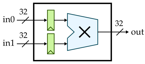
Here is the interface for our single-cycle multiplier.
module imul_IntMulScycleV1
(
  input  logic        clk,
  input  logic        reset,

  input  logic [31:0] in0,
  input  logic [31:0] in1,
  output logic [31:0] out
);
Our single-cycle multiplier takes two 32-bit input values and produces a 32-bit output value. Notice our coding conventions. We prefix all Verilog module names with the corresponding directory path, we use CamelCase for Verilog module names, and we align all port names. We can implement this single-cycle multiplier flat (i.e., directly use behavioral modeling without instantiating any child modules) or structurally (i.e., instantiate child modules). Here is what a flat implementation might look like:
//----------------------------------------------------------------------
// Input Registers (sequential logic)
//----------------------------------------------------------------------

logic [31:0] in0_reg;
logic [31:0] in1_reg;

always @( posedge clk ) begin
  if ( reset ) begin
    in0_reg <= 32'b0;
    in1_reg <= 32'b0;
  end
  else begin
    in0_reg <= in0;
    in1_reg <= in1;
  end
end

//----------------------------------------------------------------------
// Multiplication Logic (combinational logic)
//----------------------------------------------------------------------

always @(*) begin
  out = in0_reg * in1_reg;
end
Note that we are using an always @(posedge clk) to model sequential
logic and an always @(*) to model combinational logic. Always be very
explicit about what part of your design is sequential and what part is
combinational. Always use non-blocking assignments (<=) in an
always @(posedge clk) and always use blocking assignments (=) in
an always @(*). At least when getting started, try to avoid including
too much combinational logic in your sequential blocks. You can also
include simple combinational logic directly in an assign statement. So
we could replace the always @(*) with the following:
assign out = in0_reg * in1_reg;
Here is how we might implement the two registers structurally by
instantiating the vc_ResetReg component which is provided in vc/regs.v.
logic [31:0] in0_reg;

vc_ResetReg#(32,0) in0_reg_
(
  .clk   (clk),
  .reset (reset),
  .d     (in0),
  .q     (in0_reg)
);

logic [31:0] in1_reg;

vc_ResetReg#(32,0) in1_reg_
(
  .clk   (clk),
  .reset (reset),
  .d     (in1),
  .q     (in1_reg)
);
We specify the register bitwidth and reset value as parameters using the
#() syntax. To use the vc_ResetReg module you will need to add the
following to the top of your Verilog RTL file:
`include "vc/regs.v"
Go ahead and implement our first single-cycle multiplier in
imul/IntMulScycleV1.v. You can implement the registers either flat or
structurally, and you can implement the actual multiplication logic
either using an always @(*) or an assign statement.
Verilog-Based Ad-Hoc Test for Single-Cycle Multiplier
Now that we have implemented our single-cycle multiplier, we need to test
it. Let’s start by trying the Verilog-based ad-hoc test harness located
in imul/imul-v1-adhoc-test.v. Take a few minutes to look at this test
harness.
`include "imul/IntMulScycleV1.v"

module top;

  // Clocking

  logic clk = 1;
  always #5 clk = ~clk;

  // Instaniate the design under test

  logic        reset = 1;
  logic [31:0] in0;
  logic [31:0] in1;
  logic [31:0] out;

  // Instantiate the multiplier

  imul_IntMulScycleV1 imul
  (
    .clk   (clk),
    .reset (reset),
    .in0   (in0),
    .in1   (in1),
    .out   (out)
  );

  // Simulate the integer multiplier

  initial begin

    // Dump waveforms

    $dumpfile("imul-v1-adhoc-test.vcd");
    $dumpvars;

    // Reset

    #11;
    reset = 1'b0;

    // Cycle 1

    in0 = 32'h02;
    in1 = 32'h03;
    #10;
    $display( " cycle = 1: in0 = %x, in1 = %x, out = %x", in0, in1, out );

    ...

    $finish;
  end

endmodule
The test harness includes some logic to generate a clock, instantiates the design under test, and uses an initial block to set the input signals and display the output signals. Icarus Verilog is an open-source Verilog simulator. You can compile and run this test harness along with our single-cycle multiplier using Icarus Verilog as follows:
% mkdir -p $TOPDIR/build
% cd $TOPDIR/build
% iverilog -g2012 -I .. -o imul-v1-adhoc-test ../imul/imul-v1-adhoc-test.v
% ./imul-v1-adhoc-test
Notice how we are building our simulator in a separate build directory
to keep generated files separate from our soure files.
Python-Based Ad-Hoc Test for Single-Cycle Multiplier
The Icarus Verilog simulator is quite slow, only supports a pretty old version of Verilog, and does not produce terribly helpful error messages. Furthermore, writing test benches in Verilog is very tedious and not particularly fun. In this course, we will be using the Verilator simulator which is very fast, supports some of SystemVerilog, and produces much better error messages. In addition we will be using Python to write all of our test benches. Python is fun!
We need to write a PyMTL3 wrapper for every component we want to test
using Python. Take a look at the PyMTL3 wrapper for our single-cycle
multiplier located in imul/IntMulScycleV1.py:
from pymtl3 import *
from pymtl3.passes.backends.verilog import *

class IntMulScycleV1( VerilogPlaceholder, Component ):
  def construct( s ):
    s.in0 = InPort ( 32 )
    s.in1 = InPort ( 32 )
    s.out = OutPort( 32 )
The PyMTL3 wrapper is a Python class that inherits from the
VerilogPlaceholder and Component base classes. It includes one
construct method which instantiates all of the ports. The port names
and bitwidths in the wrapper should exactly match the port names in the
Verilog module. PyMTL3 can figure out if there is a clk and reset
port automatically.
Now let’s look at the Python test bench located in
imul/imul-v1-adhoc-test.py:
from sys import argv

from pymtl3  import *
from pymtl3.passes.backends.verilog import *

from IntMulScycleV1 import IntMulScycleV1

# Get list of input values from command line

in0_values = [ int(x,0) for x in argv[1::2] ]
in1_values = [ int(x,0) for x in argv[2::2] ]

# Create and elaborate the model

model = IntMulScycleV1()
model.elaborate()

# Apply the Verilog import passes and the default pass group

model.apply( VerilogPlaceholderPass() )
model = VerilogTranslationImportPass()( model )
model.apply( DefaultPassGroup(linetrace=True,textwave=True,vcdwave="imul-v1-adhoc-test") )

# Reset simulator

model.sim_reset()

# Apply input values and display output values

for in0_value,in1_value in zip(in0_values,in1_values):

  # Write input value to input port

  model.in0 @= in0_value
  model.in1 @= in1_value
  model.sim_eval_combinational()

  # Tick simulator one cycle

  model.sim_tick()

# Tick simulator three more cycles and print text wave

model.sim_tick()
model.sim_tick()
model.sim_tick()
model.print_textwave()
The test bench gets some input values from the command line, instantiates the design under test, applies some PyMLT3 passes, and then runs a simulation by setting the input values and displaying the output value.
You can run this test harness along with our single-cycle multiplier as follows:
% cd $TOPDIR/build
% python ../imul/imul-v1-adhoc-test.py 2 3 16 2
Notice how we are still building our simulator in a separate build
directory to keep generated files separate from our soure files. The
PyMTL3 framework takes care of using Verilator to compile your Verilog
RTL before running the Python test bench. The ad-hoc test will display a
line trace:
1r 00000000|00000000(00000000 00000000)00000000
2r 00000000|00000000(00000000 00000000)00000000
3: 00000002|00000003(00000000 00000000)00000000
4: 00000010|00000002(00000002 00000003)00000006
5: 00000010|00000002(00000010 00000002)00000020
6: 00000010|00000002(00000010 00000002)00000020
7: 00000010|00000002(00000010 00000002)00000020
A line trace shows the state of the design with fixed width fields and exactly one line per cycle. You can see the input values 2,3 being sent to the multiplier on cycle 3 and the corresponding result produced on cycle 4. Take a closer look at the line-tracing code which is in the Verilog RTL to see how this line trace is produced before continuing.
The ad-hoc test also displays a text-based waveform. The line trace and text-based waveform are isomorphic; they are showing the same information in two different ways.
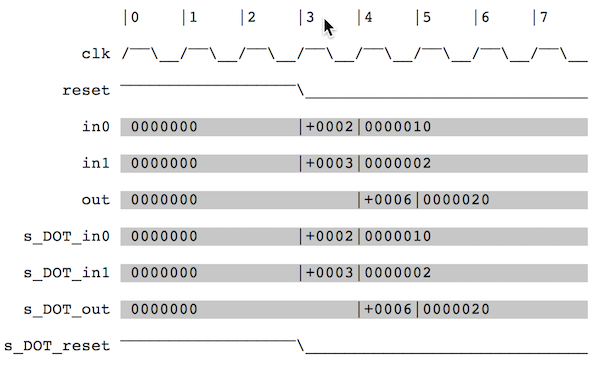
Finally, the ad-hoc test also generates a VCD file that enables much more detailed waveform visualization using gtkwave.
% cd $TOPDIR/build
% gtkwave imul-v1-adhoc-test.vcd
Verilog RTL for Single-Cycle Multiplier with Valid Bit
Now that we know the basics of Verilog RTL modeling and how to simulate these models, let’s improve our multiplier by adding support for a valid bit. A valid bit will enable the multiplier to know when valid data is available at the input and to pass this information on to the output. The hardware we wish to implement looks like this:
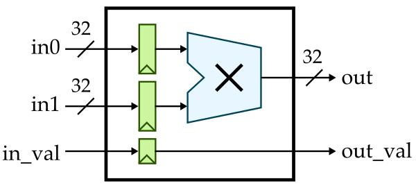
Here is the interface for our single-cycle multiplier with valid bit:
module imul_IntMulScycleV2
(
  input  logic        clk,
  input  logic        reset,

  input  logic        in_val,
  input  logic [31:0] in0,
  input  logic [31:0] in1,

  output logic        out_val,
  output logic [31:0] out
);
Copy your implementation from imul/IntMulScycleV1.v into
imul/IntMulScycvleV2.v and modify it so that it correctly implements
the valid bit. Then use the following ad-hoc test to verify it functions
correctly. Look carefully to ensure the valid bit at the output is only
high when the output data is indeed valid.
% cd $TOPDIR/build
% python ../imul/imul-v2-adhoc-test.py 2 3 16 2
Verilog RTL for Single-Cycle Multiplier with Streaming Interface
The V1 and V2 single-cycle multipliers are latency-sensitive. This means if we want to develop a component that uses these multipliers, our component’s logic would need to be hard-coded to expect the output value one cycle after we set the input values. If we wanted to swap in a different multiplier implementation (e.g., a multi-cycle iterative implementation or a pipelined implementation) we would need to rewrite all of the logic in our component. Testing comopnents that are latency-sensititive is also cumbersome since we need to carefully verify the exact expected outputs every cycle.
In this course, we will make extenstive use of latency-insensitive streaming interfaces. Such interfaces use a val/rdy microprotocol which will enable other logic to always function correctly regardless of how many cycles a component requires.
VAL/RDY MICROPROTOCOL: Assume we have a producer that wishes to send a message to a consumer using the val/rdy micro-protocol. At the beginning of the cycle, the producer determines if it has a new message to send to the consumer. If so, it sets the message bits appropriately and then sets the valid signal high. Also at the beginning of the cycle, the consumer determines if it is able to accept a new message from the producer. If so, it sets the ready signal high. At the end of the cycle, the producer and consumer can independently AND the valid and ready signals together; if both signals are true then the message is considered to have been sent from the producer to the consumer and both sides can update their internal state appropriately. Otherwise, we will try again on the next cycle. To avoid long combinational paths and/or combinational loops, we should avoid making the valid signal depend on the ready signal or the ready signal depend on the valid signal. If you absolutely must, you can make the ready signal depend on the valid signal (e.g., in an arbiter) but it is considered very bad practice to make the valid signal depend on the ready signal. As long as you adhere to this val/rdy microprotocol, composing modules via the stream interfaces should not cause significant timing issue
Here is how we can implement a single-cycle multiplier with a latency-insenstiive streaming interface:
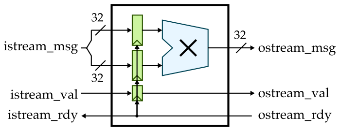
Here is the interface for this single-cycle multiplier:
module imul_IntMulScycleV3
(
  input  logic        clk,
  input  logic        reset,

  input  logic        istream_val,
  output logic        istream_rdy,
  input  logic [63:0] istream_msg,

  output logic        ostream_val,
  input  logic        ostream_rdy,
  output logic [31:0] ostream_msg
);
Notice that we have a valid signal (val), a ready signal (rdy), and a
message (msg) associated with both the input stream and the output
stream. We have provided the implementation of this multiplier for you.
Take a look in imul/IntMulScycleV3.v. The PyMTL3 wrapper is located in
imul/IntMulScycleV3.py and looks like this:
from pymtl3 import *
from pymtl3.passes.backends.verilog import *
from pymtl3.stdlib.stream.ifcs import IStreamIfc, OStreamIfc

class IntMulScycleV3( VerilogPlaceholder, Component ):
  def construct( s ):
    s.istream = IStreamIfc( Bits64 )
    s.ostream = OStreamIfc( Bits32 )
Once we start using streaming interfaces we can take advantage of stream
sources to send messages to our design and stream sinks to accept
messages from our design and check that they are correct. Here is our new
test harness in imul/imul-v3-adhoc-test.py:
class TestHarness( Component ):

  def construct( s, imsgs, omsgs ):

    # Instantiate models

    s.src  = StreamSourceFL( Bits64, msgs=imsgs, initial_delay=0, interval_delay=0 )
    s.sink = StreamSinkFL  ( Bits32, msgs=omsgs, initial_delay=0, interval_delay=0 )
    s.imul = IntMulScycleV3()

    # Connect

    s.src.ostream  //= s.imul.istream
    s.imul.ostream //= s.sink.istream

  def done( s ):
    return s.src.done() and s.sink.done()

  def line_trace( s ):
    return s.src.line_trace() + " > " + s.imul.line_trace() + " > " + s.sink.line_trace()
The test harness instantiates a stream source, multiplier, and stream sink. It then hooks the streaming interfaces up. Let’s try it out.
% cd $TOPDIR/build
% python ../imul/imul-v3-adhoc-test.py 2 3 16 2
The line trace looks very similar to our previous version, but to really
see the difference we need to introduce some back-pressure into our
design where the consumer is not ready. You can do this by changing the
initial_delay and interval_delay for the stream sink. Experiment with
different values and observe how the back-pressure changes the
line-trace. For streaming interfaces, the line trace works like this:
.= val/rdy interface is not valid and not ready#= val/rdy interface is valid but not ready- space = val/rdy interface is not valid and ready
- message is shown when it is actually transferred across interface
You will be implementing two multi-cycle iterative multipliers in lab 1 which make use of stream interfaces. We will then be able to use these multipliers in the processor you design in lab 2. If the processor correctly adheres to the val/rdy micro-protocol then it will function correctly regardless of the latency of the multiplier.